By Laurence Claus
Fasteners are universally one of the most utilized components in the world. Most products have to be held together in some manner, so that fasteners are everywhere. Since they are so common, nearly everyone has some degree of experience with them, whether pounding a nail to hold a board in-place, turning a lug nut to snug or remove a wheel, or retightening a screw to cinch something back up tight. Over a lifetime, however, not every experience with a fastener is a positive one. Consider the following three fastening application failures; 1. Driving a screw into plastic and having the plastic component break. 2. Connecting two pieces of thin sheet metal with a screw only to have it strip out. 3. Attempting to connect two dissimilar materials together such as steel and aluminum, and have the screw embed itself deeply into the aluminum top plate, endangering the joint and scarring the appearance.
What do these three examples have in common? They, along with a handful of others, represent applications where fastening options are either limited or difficult. In this series, we will investigate three of these applications that have long vexed engineers, designers, and installers alike. In Part 1 we will look at thread forming into thin sheets and why a robust self-piercing, thread-forming solution is so desirable. In Part 2, we will explore why fastening into thin-walled plastic structures is so challenging and in Part 3 why hybrid or mixed material joints can be very difficult.
There are literally thousands of applications that employ the use of thin metal sheets. Sometimes these sheets are purely aesthetic such as the many sheets of formed copper that attach to underlying supporting spars and give us the Statue of Liberty (See Figure 1). Sometimes they are structural such as the outer skin on an airplane, where the thin sheets are connected together over underlying spars and give the fuselage its strength and rigidity (See Figure 2). Sometimes they are functional such as the thin sheets that are connected to supporting columns to make a standard household metal shelving unit. Often, however, thin sheets are utilized to provide two or all of these functions simultaneously. Take for example a typical unit body automobile, hundreds of individual thin metal sheets and components are fastened together to make the body. This body defines the shape and aesthetics of the automobile, provides the structure for the passenger compartment, and makes up functional componentry like doors, hoods, and deck lids (See Figure 3).

Figure 1: Example of Thin Metal Sheets Used for Aesthetic Purposes
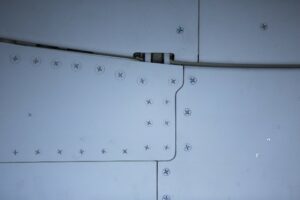
Figure 2: Example of Aircraft Screws Connecting Fuselage Panels

Figure 3: Example of Pick-up Truck Body
Perhaps some of the most iconic thin sheet applications include HVAC applications where networks of thin metal ducts must be interconnected and hung to supply conditioned air throughout buildings where people live and work (See Figure 4). Appliances also utilize thin metal sheets to provide both the “envelope” that defines the shape and size of the machine but also the structure to support components and contents (See Figure 5).
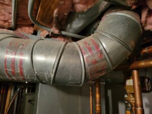
Figure 4: Example of Residential Ductwork

Figure 5: Household Appliances Outer Case Defined by Thin Metal Sheets
With so many widespread and common applications, why does this one fall on a list of the most difficult ones to solve? The essential clue to answer this question lies in the description of the application itself and the use of the word “thin” metal sheets. Since the sheets can be very thin they do not provide much depth for a threaded fastener to engage. Thus, the resulting joint is often prone to easy stripping and pull-out.
Traditionally thin metal sheets have been joined with machine screws and nuts, spot welds, or rivets. In instances where the item is being assembled in mass production, one or more of these methods might be perfectly suitable and convenient. While these often make excellent solutions under such conditions, they may not be at all practical, convenient, or feasible when access is limited to a single side of the application, or it is being field assembled. Imagine for a moment an HVAC ductwork installer having to lug a welding rig into a confined ceiling space. In addition to being inconvenient, it is likely not feasible.
When the installation requires the use of a threaded, self-tapping fastener, success or failure rests on how much of the thread can be engaged in the thickness of the sheet. The more thread that can be engaged, the more robust the fastened joint. In some instances if the sheet is very “thin” less than one pitch of thread may be engaged. When so few threads are engaged the risk of thread stripping is high, the ability of the thread to generate an axial load before failing is quite low, and pull-out of the fastener is easy. Of course, the thinner the sheet the more pronounced these problems become.
In the real world, this means that applications that utilize thin sheet thicknesses without well controlled installation processes are particularly prone to stripping. This is the most significant challenge for installation and assembly processes that are done by hand, such as the field installation of sheet metal ductwork. One might argue that it is good enough to just have a couple of screws engaged, stripped or not, to hold the duct sections in-place. Unfortunately such a notion fails to recognize that such joints do not possess clamping load, and are, thus, subject to loosening, falling out, or creating an annoying squeak or rattle at that ductwork juncture when air is blowing through it.
To illustrate this point consider a standard 6 inch diameter circular HVAC duct. It will be made of 26 gage material, which is equivalent to .0187 inches thick. Assuming a routine connection of two circular ducts where one end slides over the other, the thickness is, thus, doubled to .0374 inches thick. When designing a screw, the spacing between the threads is known as the Thread Pitch. For fastening into thin sheets, one would choose a screw with the threads spaced more closely together. So in this instance, a standard sheet metal screw for this application would be a #8-32 screw with either a PhillipsÒ Pan or Hex Washer head. The “32” in this designation represents the number of threads found in one inch with this spacing. If we simplify that to just the spacing between one thread, which is the Thread Pitch, we would discover it to be 0.794 inches. Therefore, in this example there is only about one-half of a thread pitch actually engaged in the thin ductwork. This clearly illustrates how marginal the joint really is. With only one-half of a pitch engaged, stripping is almost certain if too much torque is applied and pull-out resistance will be minimal.
Another challenge confronted by these applications is access. Take for example the previous illustration of HVAC ductwork, when two sections must be connected to one another, the only access is from the outside. Therefore, this application must rely on a one-sided fastening method. This could be a process like drilling a hole and using a blind rivet. Although certainly an effective method, it is time consuming and often impractical when the assembler is working in tight or confined quarters. Therefore, many of these applications require a screw that easily pierces thin metal sheet and forms its own thread. Once again, however, with only a small amount of thread engaged, the quality and reliability of these joints is often questionable.
The third challenge confronted by installers is the installation technique itself. If the joint is being assembled in the field like the HVAC joint illustrated above would be, the risk of thread strippage is very high. The lack of control parameters on both the tool and installer are great and, more likely than not, unless the installer exhibits exceptional finesse and skill, many of these joints are likely to be compromised. In a mass production assembly setting where the control parameters can be more precisely regulated, the number of compromised joints likely decreases but still remains problematic with so little thread actually engaged. Additional installation challenges arise in piercing the sheets. When the sheet thickness is thin, the installer may be able to simply utilize a sharp point on the end of the screw in tandem with some end load pressure to pierce the sheet. However, when the sheet thickness begins to increase, the end load required becomes arduous, and can quickly lead to installer fatigue and “no-start” conditions (when the installer is unable to get the screw to engage and start). Additionally the higher amount of end load often leads to deflection and damage of the top sheet of material. To counter this problem some applications employ screws with drill points or provide a pilot or clearance hole in part or all of the joint.
So, with these challenges prevalent in this application, how does one overcome them? Unfortunately there is no single, universal answer to that question, and each application is uniquely different. In other words, the fastener engineer must review all aspects of the joint including thickness, material, where it will be installed, what tool will be used to install it, what surrounding conditions will be present, and the general expertise that the installer must possess, to determine the best solution.
Fortunately, today there are many fastening solutions that address these challenges. These include self-piercing rivets, rivet nuts, solid rivets, blind rivets, pin and collar assemblies, weld nuts, J-clips, machine screws and nuts, sheet metal screws, self-drilling screws, self-extruding screws, flow drilling screws, and mechanical joining techniques. Although this is a long list, many of these solutions add cost and complexity and fail to answer all the parts that make this such a difficult application. For example, machine screw and nut assemblies are a common way of connecting thin sheets but add the cost of an additional component and require clear access to both sides of the joint.
Knowing about these solutions and products, their strengths and weaknesses, will provide a distributor with an opportunity to impress their customers and establish themselves with a reputation as a solution provider and not just a “me-too” vendor of class C items. However, even more important than knowing about all the options is the ability to discern which provides the best solution. Even though there are likely to be more than one feasible solution, the good distributor or application engineer will point the customer towards the best one.
The first, and perhaps best overall solution is friction drilling technology often referred to with screws as “flow drill screwing”. This method was first experimented with in the early 1920s but didn’t really emerge as a feasible option until the 1980s. Initially the technology was developed for thicker panels and incorporated a separate friction drilling and tapping operation. In the late 1990s, an innovative German fastener manufacturer, EJOT GmbH, incorporated self-piercing, friction drilling, and self-threading technology all into one screw, the EJOT FDS® screw (See Figure 6).
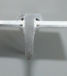
Figure 6: EJOT FDS® Screw Piercing an Aluminum Top Sheet and Steel Bottom Sheet
The clear advantage of these fasteners is that they come in a variety of point styles that address piercing metal sheets of varying thicknesses, and generates an extrusion that increases the joint thickness by two to three times. This, effectively, provides maybe three or more thread pitches of thread engagement, guaranteeing a reliable joint that can be successfully engineered to prevent the screw from stripping. Additional advantages of this screw include its speed of installation (a few seconds), the ability to self-pierce or utilize an established pilot hole, ability to fasten more than two layers of sheet in the same joint stack, and be installed from a single side.
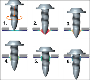
Figure 7: EJOT FDS® Screw -How it Works
The process is relatively straight forward (See Figure 7). The screw is rotated at high speed above its installation location. The specially designed tip generates a lot of friction and locally heats the area around the tip. Once this localized zone is sufficiently heated and the mechanical properties of the material made favorable to forming, an end load is applied and the material flows mostly forward to create an extrusion or boss below the bottommost sheet. The threaded portion of the screw follows the tip into this extruded zone forming internal threads. These threads, in combination with the threads formed in the original sheet thickness, provide excellent tightening margin so that the screw can be torqued to generate a strong clamping load without stripping.
Prior to the introduction of flow drilling technology, several companies developed self-extruding screws. Early versions did not always perform significantly better than standard sheet metal screws, but improved, better performing, proprietary versions like EJOT’s SHEETtracs® have come to the market in recent years. These screws require a pilot hole smaller in diameter than the actual screw diameter, perhaps about the diameter of the core, and have special tip designs that push the remaining material between the pilot hole diameter and outer diameter of the screw into an extrusion. Although the forming mechanism is quite different than flow drill screwing, the end result is similar with the creation of an extrusion that increases joint thickness. Because the material available to form the extrusion is significantly less than the full pierced cross section obtained with flow drill screwing, the height of the extrusion is considerably less. These screws also do not address the self-piercing need as they require a pre-punched or drilled pilot hole.
In applications where the sheet thickness is greater and too thick to easily accommodate piercing, drill screws work well. These screws incorporate a drill point on the tip that self-drills a properly sized pilot hole. The threads that follow the tip form internal threads. In cases where the sheet thickness is several thread pitches thick, these screws provide a good solution. However, if the sheet thickness is thin, drill screws do not perform much better than sheet metal screws.
Finally, the last solution that checks most of the challenge boxes are self-piercing rivets. Such rivets get their name from the fact that no pilot hole needs to be pre-punched or drilled in the connecting sheets. The rivet itself is designed to pierce the top sheet and embed itself into the lower sheet (See Figure 8). This is a fast installation process utilizing special equipment. Different semi-tubular or solid rivet versions exist, and different material or material processing allows these fastener elements to be applied in a variety of materials and thicknesses. One of the greatest disadvantages of this solution, however, is that it requires both a top and bottom tool. This means that the installer must have easy access to both sides. Also, the installation equipment is bulky enough that it is simply not practical as a field solution for attaching thin sheet like the HVAC illustration that has been referred to several times in this article.
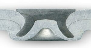
Figure 8: Example of Self-Piercing Rivet in Cross Section
In summary, attaching thin sheet is such a common fastening application that many options have been developed and evolved over the years. The fact remains, however, that even with all of these potential solutions the application itself is still one of the trickiest in fastener engineering. Therefore, it is not wise for any distributor or user to, proverbially, hitch their horse to a single wagon. Instead, distributors that make their reputation on supplying fastener engineering and design assistance to their customers should be aware of all the options and strive to direct their customers into the solution that best fits the application.
Distributor’s Link Magazine is an award-winning, multimedia publication dedicated to reporting, educating, and promoting the fastener industry since 1976.
Contact: Tracey Lumia


